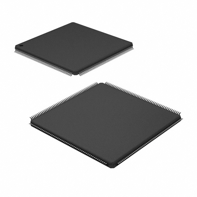
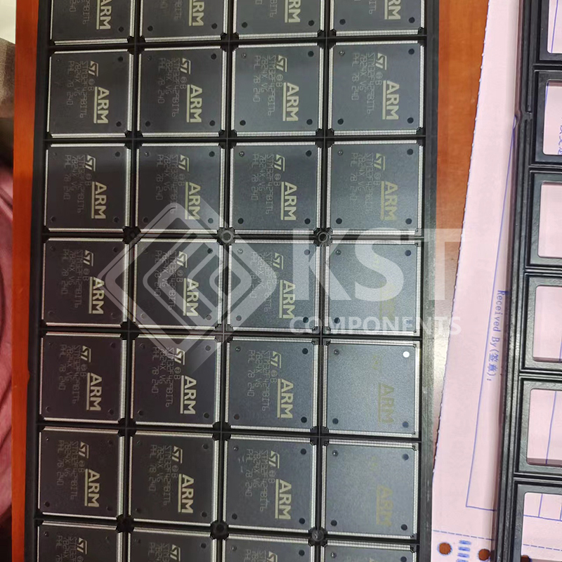
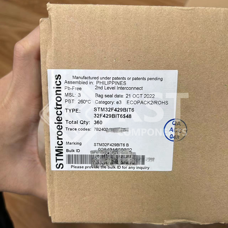
STM32F429BIT6

The STM32F427xx and STM32F429xx devices are based on the high-performance Arm®
Cortex®-M4 32-bit RISC core operating at a frequency of up to 180 MHz. The Cortex-M4
core features a Floating point unit (FPU) single precision which supports all Arm® singleprecision data-processing instructions and data types. It also implements a full set of DSP
instructions and a memory protection unit (MPU) which enhances application security.
The STM32F427xx and STM32F429xx devices incorporate high-speed embedded
memories (Flash memory up to 2 Mbyte, up to 256 Kbytes of SRAM), up to 4 Kbytes of
backup SRAM, and an extensive range of enhanced I/Os and peripherals connected to two
APB buses, two AHB buses and a 32-bit multi-AHB bus matrix.
All devices offer three 12-bit ADCs, two DACs, a low-power RTC, twelve general-purpose
16-bit timers including two PWM timers for motor control, two general-purpose 32-bit timers.
They also feature standard and advanced communication interfaces.
• Up to three I2Cs
• Six SPIs, two I2Ss full duplex. To achieve audio class accuracy, the I2S peripherals can
be clocked via a dedicated internal audio PLL or via an external clock to allow
synchronization.
• Four USARTs plus four UARTs
• An USB OTG full-speed and a USB OTG high-speed with full-speed capability (with the
ULPI),
• Two CANs
• One SAI serial audio interface
• An SDIO/MMC interface
• Ethernet and camera interface
• LCD-TFT display controller
• Chrom-ART Accelerator™.
Advanced peripherals include an SDIO, a flexible memory control (FMC) interface, a
camera interface for CMOS sensors. Refer to Table 2: STM32F427xx and STM32F429xx
features and peripheral counts for the list of peripherals available on each part number.
The STM32F427xx and STM32F429xx devices operates in the –40 to +105 °C temperature
range from a 1.7 to 3.6 V power supply.
The supply voltage can drop to 1.7 V with the use of an external power supply supervisor
(refer to Section 3.17.2: Internal reset OFF). A comprehensive set of power-saving mode
allows the design of low-power applications.
The STM32F427xx and STM32F429xx devices offer devices in 8 packages ranging from
100 pins to 216 pins. The set of included peripherals changes with the device chosen.


Download Details PDF

Notice:

In stock will ship in 2 days. Real-time inventory pls confirm with us.

INQUIRY ONLINE


    SPECIFICATION

    • Core: Arm® 32-bit Cortex®-M4 CPU with FPU,
    Adaptive real-time accelerator (ART
    Accelerator™) allowing 0-wait state execution
    from Flash memory, frequency up to 180 MHz,
    MPU, 225 DMIPS/1.25 DMIPS/MHz
    (Dhrystone 2.1), and DSP instructions
    • Memories
    – Up to 2 MB of Flash memory organized into
    two banks allowing read-while-write
    – Up to 256+4 KB of SRAM including 64-KB
    of CCM (core coupled memory) data RAM
    – Flexible external memory controller with up
    to 32-bit data bus: SRAM, PSRAM,
    SDRAM/LPSDR SDRAM, Compact
    Flash/NOR/NAND memories
    • LCD parallel interface, 8080/6800 modes
    • LCD-TFT controller with fully programmable
    resolution (total width up to 4096 pixels, total
    height up to 2048 lines and pixel clock up to
    83 MHz)
    • Chrom-ART Accelerator™ for enhanced
    graphic content creation (DMA2D)
    • Clock, reset and supply management
    – 1.7 V to 3.6 V application supply and I/Os
    – POR, PDR, PVD and BOR
    – 4-to-26 MHz crystal oscillator
    – Internal 16 MHz factory-trimmed RC (1%
    accuracy)
    – 32 kHz oscillator for RTC with calibration
    – Internal 32 kHz RC with calibration
    • Low power
    – Sleep, Stop and Standby modes
    – VBAT supply for RTC, 20×32 bit backup
    registers + optional 4 KB backup SRAM
    • 3×12-bit, 2.4 MSPS ADC: up to 24 channels
    and 7.2 MSPS in triple interleaved mode
    • 2×12-bit D/A converters
    • General-purpose DMA: 16-stream DMA
    controller with FIFOs and burst support
    • Up to 17 timers: up to twelve 16-bit and two 32-
    bit timers up to 180 MHz, each with up to 4
    IC/OC/PWM or pulse counter and quadrature
    (incremental) encoder input
    • Debug mode
    – SWD & JTAG interfaces
    – Cortex-M4 Trace Macrocell™
    • Up to 168 I/O ports with interrupt capability
    – Up to 164 fast I/Os up to 90 MHz
    – Up to 166 5 V-tolerant I/Os
    • Up to 21 communication interfaces
    – Up to 3 × I2C interfaces (SMBus/PMBus)
    – Up to 4 USARTs/4 UARTs (11.25 Mbit/s,
    ISO7816 interface, LIN, IrDA, modem
    control)
    – Up to 6 SPIs (45 Mbits/s), 2 with muxed
    full-duplex I2S for audio class accuracy via
    internal audio PLL or external clock
    – 1 x SAI (serial audio interface)
    – 2 × CAN (2.0B Active) and SDIO interface
    • Advanced connectivity
    – USB 2.0 full-speed device/host/OTG
    controller with on-chip PHY
    – USB 2.0 high-speed/full-speed
    device/host/OTG controller with dedicated
    DMA, on-chip full-speed PHY and ULPI
    – 10/100 Ethernet MAC with dedicated DMA:
    supports IEEE 1588v2 hardware, MII/RMII
    • 8- to 14-bit parallel camera interface up to
    54 Mbytes/s
    • True random number generator
    • CRC calculation unit
    • RTC: subsecond accuracy, hardware calendar
    • 96-bit unique ID