


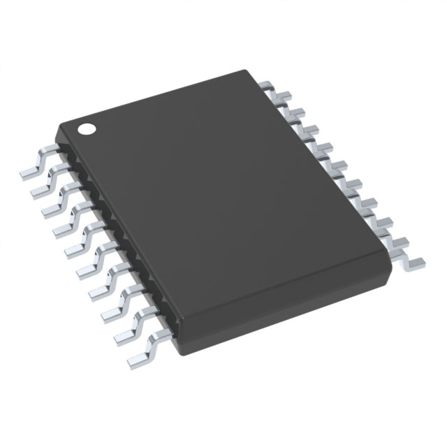
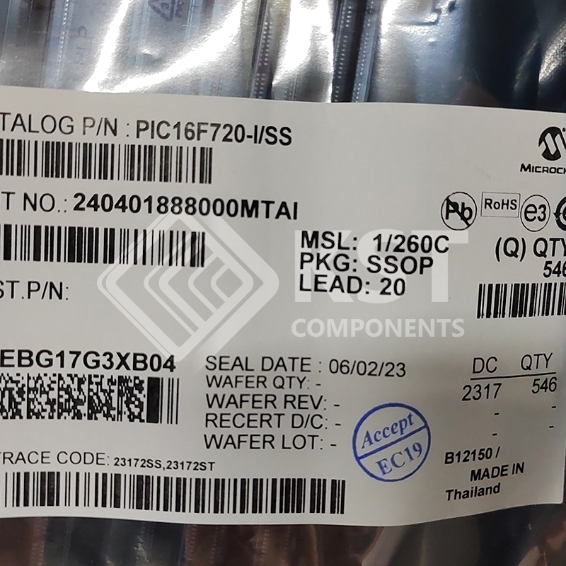
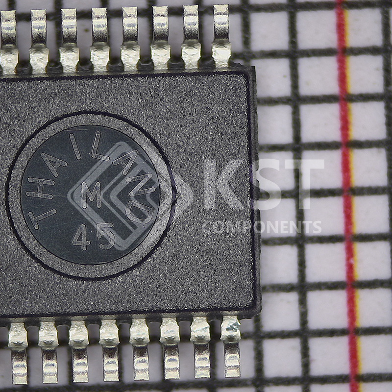
PIC16F720-I/SS
INQUIRY ONLINE
Devices Included In This Data Sheet:
High-Performance RISC CPU:
• Only 35 Instructions to Learn:
– All single-cycle instructions except branches
• Operating Speed:
– DC – 16 MHz oscillator/clock input
– DC – 250 ns instruction cycle
• Up to 4K x 14 Words of Flash Program Memory
• Up to 256 bytes of Data Memory (RAM)
• Interrupt Capability
• 8-Level Deep Hardware Stack
• Direct, Indirect and Relative Addressing modes
• Processor Self-Write/Read access to Program
Memory
Memory
• High-Endurance Flash Data Memory
– 128B of nonvolatile data storage
– 100K erase/write cycles
Special Microcontroller Features:
• Precision Internal Oscillator:
– 16 MHz or 500 kHz operation
– Factory calibrated to ±1%, typical
– Software tunable
– Software selectable ÷1, ÷2, ÷4 or ÷8 divider
• Power-Saving Sleep mode
• Industrial and Extended Temperature Range
• Power-on Reset (POR)
• Power-up Timer (PWRT)
• Brown-out Reset (BOR)
• Multiplexed Master Clear with Pull-up/Input Pin
• Programmable Code Protection
• In-Circuit Serial ProgrammingTM (ICSPTM) via Two
Pins
• Wide Operating Voltage Range:
– 1.8V to 5.5V (PIC16F720/721)
– 1.8V to 3.6V (PIC16LF720/721)
Extreme Low-Power (XLP) Features:
• Sleep Current:
– 40 nA @ 1.8V, typical
• Low-Power Watchdog Timer Current:
– 500 nA @ 1.8V, typical
Peripheral Features:
• Up to 17 I/O Pins and One Input-only Pin:
– High-current source/sink for direct LED drive
– Interrupt-on-change pins
– Individually programmable weak pull-ups
• A/D Converter:
– 8-bit resolution
– 12 channels
– Selectable Voltage reference
• Timer0: 8-Bit Timer/Counter with 8-Bit
Programmable Prescaler
• Enhanced Timer1
– 16-bit timer/counter with prescaler
– External Gate Input mode with toggle and
Single Shot modes
– Interrupt-on-gate completion
• Timer2: 8-Bit Timer/Counter with 8-Bit Period
Register, Prescaler and Postscaler
• Capture, Compare, PWM module (CCP)
– 16-bit Capture, max resolution 12.5 ns
– 16-bit Compare, max resolution 250 ns
– 10-bit PWM, max frequency 15 kHz
• Addressable Universal Synchronous
Asynchronous Receiver Transmitter (AUSART)
• Synchronous Serial Port (SSP)
– SPI (Master/Slave)
– I2C (Slave) with Address Mask