


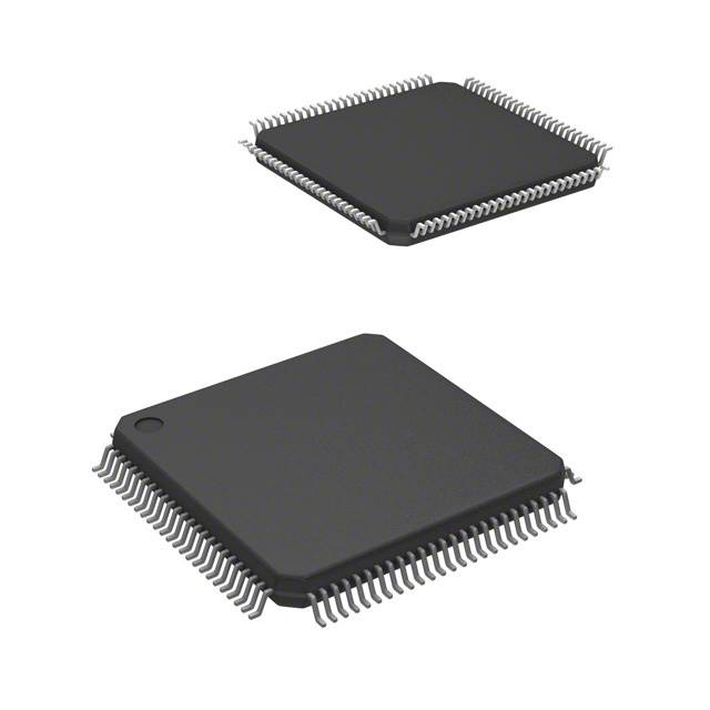
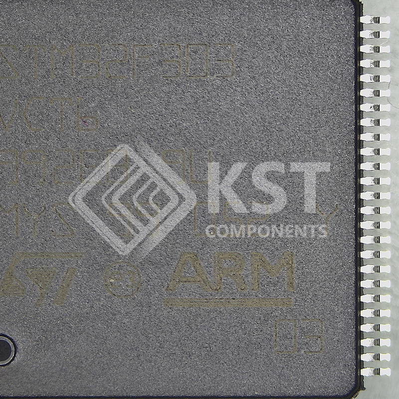
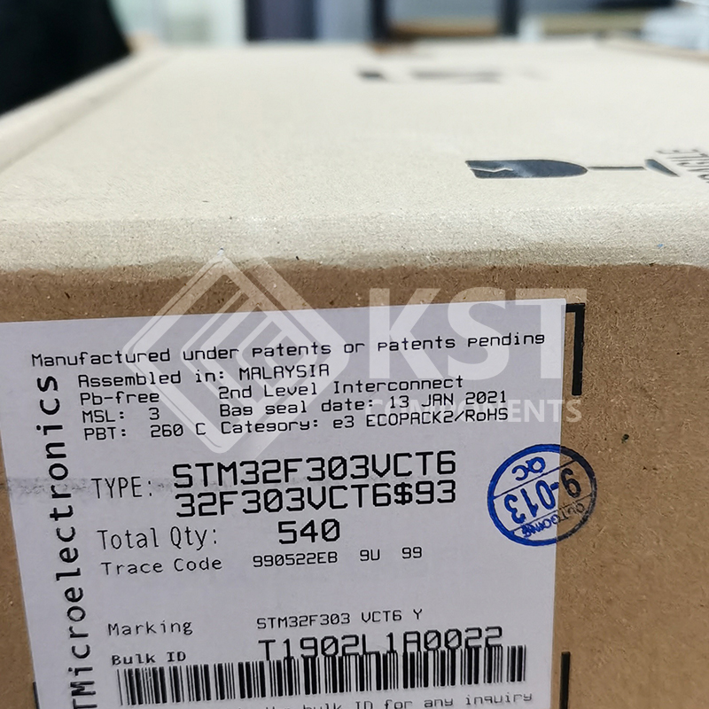
STM32F303VCT6
INQUIRY ONLINE
• Core: Arm® Cortex®-M4 32-bit CPU with FPU
(72 MHz max), single-cycle multiplication and
HW division, 90 DMIPS (from CCM), DSP
instruction and MPU (memory protection unit)
• Operating conditions:
– VDD, VDDA voltage range: 2.0 V to 3.6 V
• Memories
– 128 to 256 Kbytes of Flash memory
– Up to 40 Kbytes of SRAM, with HW parity
check implemented on the first 16 Kbytes.
– Routine booster: 8 Kbytes of SRAM on
instruction and data bus, with HW parity
check (CCM)
• CRC calculation unit
• Reset and supply management
– Power-on/power-down reset (POR/PDR)
– Programmable voltage detector (PVD)
– Low-power modes: Sleep, Stop and
Standby
– VBAT supply for RTC and backup registers
• Clock management
– 4 to 32 MHz crystal oscillator
– 32 kHz oscillator for RTC with calibration
– Internal 8 MHz RC with x 16 PLL option
– Internal 40 kHz oscillator
• Up to 87 fast I/Os
– All mappable on external interrupt vectors
– Several 5 V-tolerant
• Interconnect matrix
• 12-channel DMA controller
• Four ADCs 0.20 µS (up to 39 channels) with
selectable resolution of 12/10/8/6 bits, 0 to
3.6 V conversion range, single
ended/differential input, separate analog
supply from 2 to 3.6 V
• Two 12-bit DAC channels with analog supply
from 2.4 to 3.6 V
• Seven fast rail-to-rail analog comparators with
analog supply from 2 to 3.6 V
• Four operational amplifiers that can be used in
PGA mode, all terminals accessible with
analog supply from 2.4 to 3.6 V
• Up to 24 capacitive sensing channels supporting
touchkey, linear and rotary touch sensors
• Up to 13 timers
– One 32-bit timer and two 16-bit timers with
up to 4 IC/OC/PWM or pulse counter and
quadrature (incremental) encoder input
– Two 16-bit 6-channel advanced-control
timers, with up to 6 PWM channels,
deadtime generation and emergency stop
– One 16-bit timer with 2 IC/OCs, 1
OCN/PWM, deadtime generation and
emergency stop
– Two 16-bit timers with IC/OC/OCN/PWM,
deadtime generation and emergency stop
– Two watchdog timers (independent,
window)
– SysTick timer: 24-bit downcounter
– Two 16-bit basic timers to drive the DAC
• Calendar RTC with Alarm, periodic wakeup
from Stop/Standby
• Communication interfaces
– CAN interface (2.0B Active)
– Two I2C Fast mode plus (1 Mbit/s) with
20 mA current sink, SMBus/PMBus,
wakeup from STOP
– Up to five USART/UARTs (ISO 7816
interface, LIN, IrDA, modem control)
– Up to three SPIs, two with multiplexed
half/full duplex I2S interface, 4 to 16
programmable bit frames
– USB 2.0 full speed interface
– Infrared transmitter
• Serial wire debug, Cortex®-M4 with FPU ETM,
JTAG
• 96-bit unique ID