• 40 V DC maximum input voltage
• Support operating voltage range down to battery 3.2 V with VBST
• Support operating voltage range down to battery 6 V without VBST
• Low Power OFF mode with 30 µA quiescent current
• Low Power Standby mode with 29 µA quiescent current with VPRE active. LDO1 or LDO2 activation
selectable via OTP configuration. GPIO1 or GPIO2 activation selectable via SPI communication.
Power supplies
• VPRE: Synchronous buck converter with integrated FETs. Configurable output voltage and switching
frequency, output DC current capability up to 1.5 A and PFM mode for Low Power Standby mode operation.
• VCORE: Synchronous buck converter with integrated FETs. VCORE is dedicated for microcontroller core
supply. Output DC current up to 0.8 A or 1.65 A (depending on part number), output voltage range setting
from 0.8 V to 3.35 V.
• VBST: Asynchronous boost controller with external low-side switch, diode, and current sense resistor. VBST
is configurable as front-end supply to withstand low voltage cranking profiles or in back-end supply with
configurable output voltage and scalable output DC current capability.
• LDO1: LDO regulator for microcontroller I/O support with selectable output voltage between 3.3 V and 5.0 V
and up to 400 mA current capability.
• LDO2: LDO regulator for system peripheral support with selectable output voltage between 3.3 V and 5.0 V
and up to 400 mA current capability.
• VREF: High-precision reference voltage with 0.75 % accuracy for External ADC reference and internal
tracking reference.
• TRK1 and TRK2: Voltage tracking regulators with selectable output voltage between VREF, LDO2, or Internal
LDO reference. Support high-voltage protection for ECU off board operation. Each Tracker has a current
capability up to 150 mA.
System support
• Two wake-up inputs with high-voltage support for system robustness
• Two programmable GPIO with wake-up capability or HS/LS driver
• Programmable long duration timer (LDT) for system shutdown and wake-up control
• Monitoring of system voltages (Including Battery voltage monitoring) through the analog multiplexer
• Selectable wake-up sources from: WAKE/GPIO pins, LDT, or SPI activity
• Device control via 32-bit SPI interface with cyclic redundancy checks (CRC)
Compliance
• Electromagnetic compatibility (EMC) optimization techniques for switching regulators, including spread
spectrum, slew rate control, and manual frequency tuning.
• Electromagnetic interference (EMI) robustness supporting various automotive EMI test standards.
Functional safety
• Scalable portfolio from Automotive Safety Integrity Levels (ASIL) B to D
• Independent monitoring circuitry, dedicated interface for microcontroller monitoring, simple or challenger
watchdog function
• Analog built-in self-test (ABIST) and Logical Built-In Self-Test (LBIST) at start up
• Analog built-in self-test (ABIST) on demand
• Safety outputs with latent fault detection mechanism (RSTB, FS0B, FS1B)
Configuration and enablement
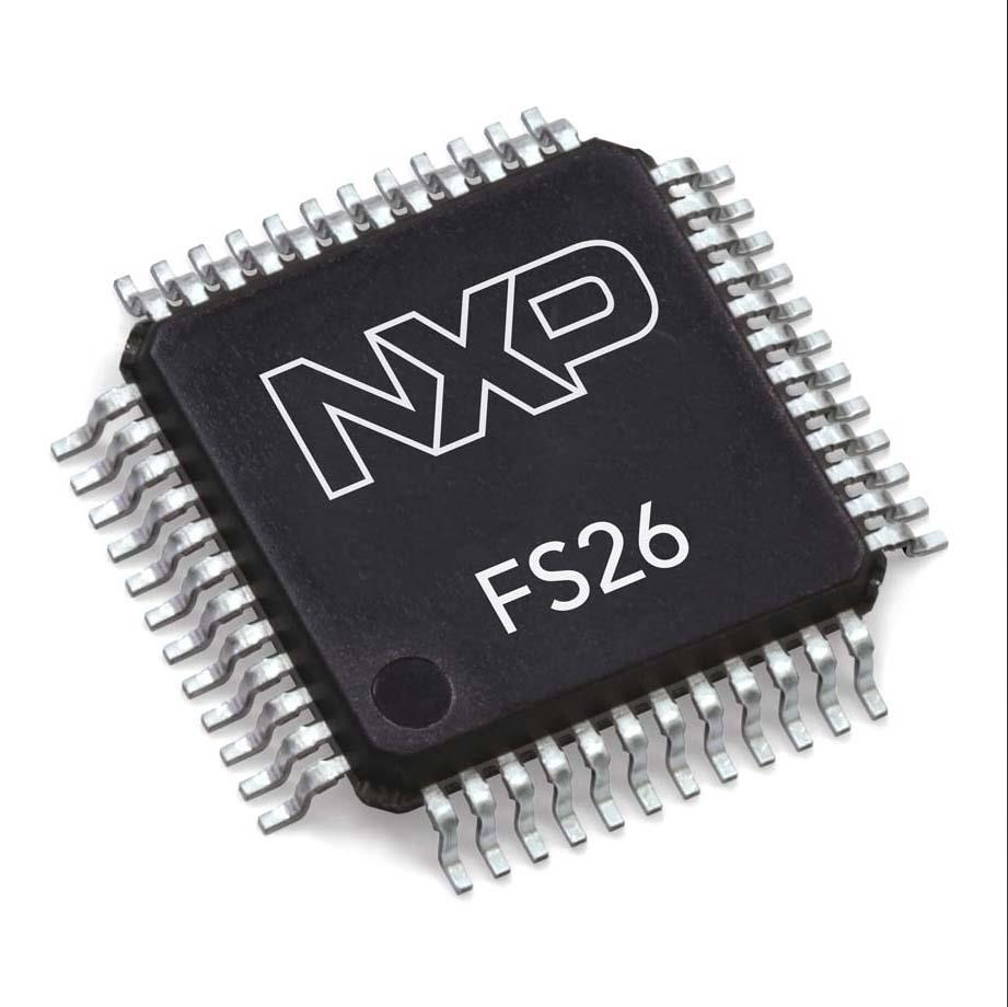
• LQFP48 pins with exposed pad for optimized thermal management
• Permanent device customization via one time programmable (OTP) fuse memory
• OTP Emulation mode for hardware development and evaluation
• Debug mode for software development, MCU programming, and debugging


